Showing posts with label JMRI. Show all posts

Monday, June 8, 2020

June 2020 Journal

Trackwork

6/21/2020 - I installed the six Tortoise drives in sections U05-U06 after first prewiring them. I thought I was going to have to cut the 1x4 support piece, but then had a brainstorm -- all I had to do was to unfasten the support piece, slide it out of the way, and then resecure it after putting the Tortoises in. Easy peasy. I need to finish wiring the other four DPDT switches before I finish the installation. I think I will also cut fascia pieces so that I only have to cut a single hole through the fascia and 1x4 for the DPDT switch to be installed. 


Electronics / JMRI

6/1/2020 - As part of the JMRI installation, I soldered extension feeder wires to the six detection coils that need to be installed in the helix. Two of them will go into the new block 300 that I need to create, two will go into block 304, and two will go into block 305. This will bump the number of helix blocks up to 12 -- six in either direction. While this seems like a lot, it's really not. Each lap around the helix is 16-17 feet long, which is comparable to other blocks on the railroad. These blocks are longer since the trains will be running at "mainline speed" here, so having longer blocks works fine. 

6/7/2020 - I finished installing the feeders in the helix and getting them hooked up to the detection coils. I also took care of splitting what was block 301 into block 300 and 301. Block 300W and 300E now cover the track from the wall to the back of helix. After programming the Watchman board, it appeared in JMRI and I was able to add the remaining indicator tracks. 

In looking at the panel, there is a "temporary" link between block 204 (on the south wall) to blocks 305W/305E. In addition, on the lower deck, block 104 connects to block 300. This is only temporary until the peninsula is added onto the layout. At that point, there will likely be blocks 104-110 and 204-210, depending on how I lay out the track and blocks. 

Because there is a temporary link, I moved the indicator tracks for blocks 300-305 so that they connect with the turnout at the end of block 204. However, when I did that and started running trains through, it looked like the train was jumping from westbound to eastbound track. After I looked at the track, I realized that I actually had a right-hand switch and not a left-hand switch. Oops. Once I adjusted that and slid the tracks down, the train went where I thought it should be. 

Here's a snapshot of the new dispatcher panel as it stands now:


6/9/2020 - I did some work on cleaning up some kinks in the helix and adding the remaining feeders. After that, I tackled wiring up the microscopic DPDT switches for use with the Tortoises in the Glenwood (U5-U6) switching district. After a few failures, I figured out that I could bend the tabs out slightly to provide some extra space for the wires. I also soldered wires onto the 6 Tortoise drives that will be installed in this area. 

NMRA Achievement Program

6/5/2020 - After many hours of operating sessions, I finally got to the point of having more than enough hours for the Chief Dispatcher achievement. I had been putting off writing up all of the additional documentation on the layout, which is all documented here on the requirements document

While some of the NMRA requirements are focused on timetable-driven operations, going through the process did make me think about how the operations would work. A few things I learned/decided:
  • The mileage I was originally planning was way more than was appropriate for my layout. Originally, I was looking at Minneapolis to Minot, which was around 450 miles. Instead, I adjusted the layout down to a much smaller portion of the CP mainline, about 240 miles. 
  • For my branchline, I figured out that I could use the Twin Cities & Western railroad as the towns on that line. I have a pretty reasonable connection on the track schematic to connect the main to the branch, as well. 
  • It made me think about the sequence of trains, especially now that I've gotten my car card system in place. 
I wrote up my documents and submitted them for review, so hopefully in a few weeks (or months), I'll have my second achievement certificate. 

Thursday, May 14, 2020

May 2020 Journal

Trackwork


5/14/2020 - I finally came up with a design for the industrial/switching district in section L5. After ordering a few more turnouts, I laid the track and I'm happy with the overall design.


This photo shows where the industries can fit into this track arrangement.


Based on a suggestion from my friend Brad, the siding at the top will actually enter the building that's going into that space, plus there will be room on the outside for a few more car spots. The bottom track towards the left is primarily space for pulling cars out of the siding to the right, but once I get some power on the track, we'll see how many cars I can reasonably pull at once without having to move the cars to the left.

5/18/2020 - After the glue dried, I finished the section by adding feeders into all the track segments and between the various turnouts. I hadn't soldered in a while and the first joints showed, but I got the hang of it after a few bad connections. Once all the wiring was done and tested, I grabbed some cars from the main yard and put them into place. It looks like I'll be able to fit 19-20 cars in the district without losing the maneuverability to hit all the tracks. Here are some photos of the finished area.


Wiring/DCC


5/19/2020 - After getting the industrial district done, I went back to the helix room to diagnose my detection issue. The helix will have a total of 12 detection blocks, 6 in each direction, starting at 300W/300E and going up the helix to 305W/305E. When I last worked on this, I was getting what seemed like false readings on 302 that wouldn't go away. I went down some rabbit holes about whether the coils were too close, the wires were crossed, etc. After disconnecting the bus wires from the terminal strip, I had an engine continue running even when its bus wire was disconnected. I then proceeded to remove the other side's bus wires one by one and found that I had mixed up one pair of feeders. After making that fix, the detection started working properly again. 

I managed to get both sides of blocks 301, 302, 303 wired up with detection coils and got them connected to the Watchman board. In addition, I happened upon the Indicator Track feature in Panel Pro and replaced the somewhat awkward icons/lights with indicator tracks. The panel looks so much better doing this. I also got a reminder of JMRI's web server feature, which is also accessible from the mobile application. This made it a lot easier to test the detection since I didn't have to keep running out to the computer.

Unfortunately, I ran out of red 20 gauge wire and I'm running low on 3M suitcase connectors, so I'll have to wait a few days to restock my supplies. That's the first spool of 500 feet that I've run through, not sure if I'll need another one after the second spool, but we'll see. I get all my wire from Del City since you can order a variety of colors individually. 

The next steps are:
  • Split block 301 into two blocks -- block 300 will cover the track from the entry to the helix room around to the back wall of the helix.
  • Add feeders to block 300W and 300E and connect up the detectors to the Watchman board, which will finish out the 8 connections on that board. 
  • Program another Watchman board to accommodate blocks 304-305W/E and future blocks that will go into the peninsula. This board will be installed in the upper deck section prior to entering the helix, since that puts it in easy reach of peninsula blocks when I get those built. 
5/25/2020 - I spent today working on wiring for the lower deck. First, I extended the RR-Cirkits Simple Serial Bus (SSB) from the boards under the main yard around the corner to the staging yards on the north wall. I then extended the Tortoise power bus, since the RR-Cirkits Motorman boards require secondary power from a power supply. I added 22 gauge wires to each of the six Tortoise drives at my work bench, since that's far simpler than trying to solder under the deck.

After that, I was able to get the lower deck's Motorman board programmed and throwing the turnout that was previously installed under the first turnout in the throat. I installed a few more Tortoise drives and got those connected to the Motorman board. I still haven't figured out a good way to install Tortoise drives with only one pair of hands, but being able to throw the turnouts via the Engine Driver app is far easier than running back and forth to the computer.

In JMRI, I added those turnouts to the panel and after swapping the two power wires on the Tortoise drives, got them in sync with the panel. Since I've got three of the 7 turnouts wired now, I could try out the Routes feature of JMRI. This lets me create a route, say IR105 for staging track 5, and trigger it from the control panel or an Engine Driver throttle. This is simpler than having to throw all the turnouts individually. I still need to figure out how to put a button of some sort on the panel to trigger the route, but the basic logic works nicely.

The next step here is to finish the remaining four turnouts and get them wired into the Motorman board. In JMRI, I'll add routes for all eight staging tracks. After that, I'll wire up the Tortoise drives on the upper deck, although I first need to rework the yard entry using the double crossover I found in Minnesota last year. 

5/27/2020 - I wired up two additional Tortoise drives in the lower staging yard this evening. I also created the other routes so that I have one route per track in the lower yard. For the upper yard, since there will be a double crossover at the entrance, I'll end up with two sets of routes: one set to reach all eight tracks from the inbound/westbound main and one set to reach the tracks from the outbound/eastbound main. 

5/28/2020 - I finished wiring the last Tortoise drives in the lower staging yard and tested out all the JMRI routes. It's nice to have that work done. 

5/30/2020 - I finished wiring up the remaining Tortoise drives at the "west" end of the main yard and got them all connected up to JMRI. I can now control the entire yard from the dispatcher panel. I am planning to do a "proof-of-concept" with the push buttons to control the crossovers locally, as well. The idea is that the yardmasters will be able to use these controls as needed, but they're also available for the dispatcher to use. 

The lower deck JMRI control panel now looks like this, for now:


5/31/2020 - I soldered feeder wires onto six detection coils to be installed in the helix. I also "discovered" that I had a staple gun in my toolbox and replaced all the unreliable duct tape with staples to secure all the feeder wires. This cleans up the wiring quite a bit and lets the detection coils stay securely in place. 

Operations


5/26/2020 - I've been working on software that ties into my train management/inventory system that was showing promise in terms of random train generation, but after thinking how much computer interaction there would be, the ongoing tracking of car numbers, etc. I decided to give that up and switch to the car order system that Dan Hinel, Hank Tenwolde, Mike Wolf, and others are using. In this system, you deal with the type of car and focus on the car spots on industry tracks. The system is self-repairing and simpler since you are only looking at car types, not car numbers. While I'll still have a database of all my cars and locomotives, the computer won't be needed for car/train management during a session. 

I went through my three industry districts and identified 55 car spots and chose various types of cars to fill those spots. After the car is picked up at the location after loading/unloading, those cars will be sent out on either eastbound or westbound manifest freight trains. This simulates the load leaving the layout going to some other location and helps rotate car usage. 

I then ran trains to all three districts to adjust the cars on each of the industry spots and brought the remaining cars back to the main yard. The next step is to rotate the cards -- setouts become pickups, holds remain holds for one "turn" -- and then run local trains to pick up the cars that need to be moved. After that, I'll run manifest trains in either direction to pick those cars up and then I'll have a corrected car cycle to continue with. It'll be more interesting as I build out the peninsula and the additional twelve switching districts I'm anticipating, but this system lets me start operating on my own without having to constantly refer back to the computer. It's ironic that as a software developer that I'm choosing a manual system over a computerized one, but I'm looking more at the ongoing maintenance and choosing a simpler system. 

Friday, May 31, 2019

Signaling options with DCC, Digitrax, and JMRI

I'm planning to eventually include signals on my layout since those are hallmarks of modern railroads. I've already started installing detection blocks as I'm building the layout, but adding signals will require more hardware and software. This page is a bookmark of videos I've found dealing with adding signals using Digitrax and JMRI.

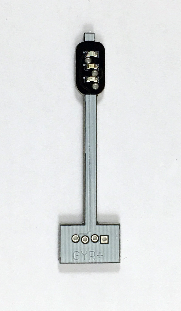
One of the recent developments is a set of simple, low cost signals that are available from Model Railroad Control Systems. These signals are just LEDs mounted on a silver piece of PC board, but they cost $14.99 for a 12 pack. Leaving out the cost of the signaling hardware, you can have a signal up for a buck and a quarter.

http://www.modelrailroadcontrolsystems.com/simple-low-cost-signals-single-high-head-12-pack/

Single high signal, looks about right for HO.  Comes in 12 pack.

These look like a good stand-in until I can afford to put in the fancy realistic signals, which will set you back a lot of money.

Virtual Signals Demo


JMRI Signaling Part 1


JMRI Signaling Part 2


JMRI Signaling Part 3


Saturday, September 29, 2018

August-September 2018 Construction Journal

August 24, 2018

After some time away from construction, I got started again on the roadbed running through the sump room. This involves drilling into the concrete to put up shelving brackets, which is always fun, especially when the drill hits something that it can't get through -- probably some rebar or something. I've got the hole between the lower staging yard cut and have started cutting the 3/4" birch that makes up the supporting framework. I'm using thicker plywood because of the changes in temperature and humidity in this unfinished part of the basement.

August 26, 2018

I got a lot done this afternoon, it just doesn't look like it. I got the remaining two brackets installed into the concrete but it looks like one will need just a little bit of a shim under the plywood. I was going to put a fourth bracket in but decided that it really wasn't necessary based on the distances involved.

I also rewired the upper section through the sump room so that all the track is detected. This involved moving the positive feeders so they all routed through the detection coil. In addition, I had to install the Anderson Powerpole connectors for the removable section. These took a little bit of work but I'm happy with the results. There are YouTube videos showing exactly how these go together, I used this one and found it immensely helpful.


The connectors are designed to only fit together one way. The metal clip is designed to crimp onto your wire, and then you push the metal clip into the end of the plastic connector. You need to be careful when crimping the wire or you can malform the metal connector and it won't fit.


Once you have the wires crimped and installed, you can slide the plastic connectors together to make a single connector.


They stay together with friction and there's a small snap when the connectors make contact. This is the standard connector being used with Free-Mo modules, as well.

I also prepped the #6 Atlas turnouts for the lower staging yard by trimming the throw bars and surrounding ties, as well as removing the ties where the rail joiners will go. For the upper yard, I laid out the tracks first and then tried to fit them to the turnout ladder, which was a mistake. This time, I'm starting with the ladder and working towards the end of the yard.

September 22, 2018

With some help from a model railroader friend, we got the benchwork completed for the sump room on the lower deck.

The birch plywood is below the level of the Homasote on the other side to make it simple to transition to the cork roadbed. 


I was going to make the lower section removable, as well, but since it's below the level of the circuit breaker panel, it turns out there was no need to do this. 


The curved piece has an outside radius of 33 5/8" and inside radius of 27 5/8", so the track will not quite make the 30" minimum radius, but it's pretty close, even for long 85' passenger cars. 


The metal shelving bracket had to be cantilevered a bit to reach the curve, but it's only a few inches of extension. 


The support within the studs is secured with 3" deck screws on either side, so it's not going anywhere. 

September 23, 2018

I wired up the detection coils on the upper deck of the sump room track, which is known as block 201 in the system. Instead of wiring the CAT5 cable directly to the coils, I made use of some 12 gang plastic barrier strips that I found on Amazon that can be cut to length. 


Once I got the wires connect here and to the RR-Cirkits Watchman board, I got the two new blocks configured in JMRI. My control panel now looks like this:


It's amazingly satisfying to see the occupancy lights turn on and off as I drive my train through the layout, such as it is. I got a second Watchman board to take care of the lower level blocks, I'll be installing those coils as I start laying the lower deck track.

September 24, 2018

After doing some layout work for the turnouts at the yard throat, we drilled holes for the Tortoise control wire and then laid the first staging yard siding. Instead of nailing the track, I'm using DAP Alex clear caulk. You only need a thin layer of caulk to hold the track down, and it dries clear. I used it on the upper modules and was happy with the results.

I also ran more wire for the Tortoise bus on the upper level and tried my hand at wiring up the DPDT switches to control the local Tortoises. Those wires are really, really small... having to use 24 gauge wire to connect these switches up.

September 29, 2018

I finished building the lower deck staging yard. The minimum track length is 12', several are almost 15' long because of how the ladder was laid out. The upper staging yard was done using track nails, which took forever and the results were less than optimal. For the lower yard, I used the DAP Alex clear caulk as an adhesive. I laid out a bead of caulk, spread it with a putty knife, and then had time to lay out the track. I used my 6' aluminum ruler as a straightedge, starting at the turnout. I used track nails on the turnouts instead of the caulk, just to avoid any unnecessary caulk getting into the turnout. This worked quite well and it took longer to trim the rail joiners than it did to put down each track. The results are shown here:


I am going to put dual bus wires on this section, since it's 36" wide. I drilled holes through the crosspieces and installed my terminal strips. I painted the rest of my backdrop material before running the bus wires.


Next steps:

  • Install backdrops on modules L6-L9
  • Secure modules to each other
  • Install terminal strip on each section
  • Cut wire holes through crosspieces
  • Run bus wires (track power, Tortoise bus)
  • Wire feeders to staging yard
  • Layout industrial district in L1-L2 and L5
Lots to do, lots to do. 

Wednesday, December 13, 2017

Connecting up JMRI

December 13, 2017

With a minimum of effort and cost, my little layout is now connected to JMRI. I picked up an old PC with Windows 7 on it from a company I had done business with. After assigning it a reserved network address, I downloaded and installed JMRI. The JMRI took care of bringing in all the dependencies on Java, no manual intervention required.

The next step was to hook up the LocoBuffer-USB interface between the computer and the layout. Again, the LocoBuffer pulled down its own drivers without any interference in my part.
I fired up JMRI PanelPro and created a new railroad profile with Digitrax and LocoBuffer as my options. I then had a brief issue because I forgot that the WiThrottle server is not the LocoNet server or the JMRI web server. However, one I remembered that, I was able to connect from my phone using the Engine Driver Android app. The reason you need a static IP is so that you always know the address of your JMRI machine.

After that, I had a little fun driving trains with my phone, which seems slightly more responsive than my UT4D throttles. However, that's not surprising given how much better my Wi-Fi is than the Digitrax wireless is.

December 14, 2017

After the initial steps of getting JMRI set up on the old PC, the next step was to try out the Watchman board to see if it could detect trains. I had already done a little work in advance; namely, getting a coil installed with the positive feeder wire running through the middle of it. Because the block is around 12' long, there are actually two positive feeders running through the same coil. I had also set up a block using insulated rail joiners. I'm installing detection on my mainline track, so the sidings are isolated from the main. While some people isolate each turnout from the surrounding track, I've decided to use a simpler approach and combine the turnout with the block. The turnout will eventually have remote control to tell me which way it's facing for signaling purposes when I get that far. 


The next step in getting the Watchman board set up is to connect the SSB Adapter to the LocoNet network. The included power adapter plugs into the wall, and then you run three wires from the terminals to the next terminal on the Watchman board. The center wire is the LocoNet, the other two are power. According to the manual, you don't have to worry about polarity on the power wires; however, I'm planning to replace this temporary SSB wire with black/green/red for simplicity. 


I ran the SSB wires to the Watchman board, plugged them in, and got a green light on both the SSB adapter and the Watchman board. 


The next step was to hook wire from the Watchman to the coil I'd installed. RR-Cirkits recommends CAT 5 twisted pair wire to eliminate extraneous noise that can affect the signal quality. This is just a temporary and ugly solder job, but it was enough to make the connection. Make sure that you don't mix up your wires or you won't get any signal at all. 


The terminals on the Watchman board are labeled "1-4" and "8-5" -- it's not written down, but pair 1 is closest to the power end of the board, and pair 8 is the closest on the other side of the board. 

The next step was to get JMRI set up to listen for the board and to start getting signals. Unfortunately, the PDF version of the Watchman manual is quite a bit different than how JMRI looks now. I did stumble on a page in the RR-Cirkits site that was updated with the more current instructions. That page is available here. One of the most important things to set is the Programming on Main option on the list of decoders. Also, when you're adding a Watchman, you click the New Loco button to get started. Even though it's not a locomotive, you'll find the RR-Cirkits (and many other) products listed there. 

I numbered this device 10001 but will probably go back and renumber it later, which is easy to do with the Decoder Pro program. Once you get past the first setup pages, the manual is somewhat helpful, but I ended up stumbling my way through. With the default settings, I put an engine on the detected track and turned on the Monitor LocoNet under the LocoNet menu. As I turned up the throttle, I could see the various commands going to the locomotive; however, no indications were present that the detector was working. After reading the manual, searching the web, and a few other things, I found the Sensitivity tab and decided to play with it. From no detection at all, I got the detection to see when the train was actually moving. There would be a messages indicating that the detection block was active, but when the throttle went to zero, the detection block went inactive. 


Through trial and error, I found that setting the sensitivity to 80 (scale of 0-255) was sufficient to detect the locomotive entering, leaving, and stopping on the track. This was a 12 foot block with two sets of feeder wires. After that, the sensor would stay "High" when the engine was anywhere in the block. 

The next step was to get this to show up on a control panel. To create a control panel, you have to use the PanelPro application instead of DecoderPro, and you can't have both running at the same time. After playing with the LayoutPro application, I found that all I needed was to create a single control panel with a single block indicator on it. This is how I did it.
  1. From the Panels menu, I chose New Panel -> Control Panel Editor.
  2. From the Add Items menu, I picked the Item Palette option. 
  3. Because I had set up the Watchman already, the item named LS1 was the block I had set up. I renamed this block U5-U6 (the name of the module) and then dragged the icon to the panel. 
  4. I then added a small block of track and some text using the item palette, to end up with a very simple control panel, shown here:


After saving this panel, you go to the File menu and choose Close Editor. One note -- clicking on the indicator will cause it to change colors, but once you start running your train, it will flip appropriately.

Once I got all this setup, I could drive my engine in and out of the detected track and see a tiny yellow indicator flip back and forth. It's amazing how exciting seeing a handful of pixels change colors can be when this all works right. 

In case you're wondering, this is what I've purchased so far to make the JMRI interface:
  • RR-Cirkits LocoBuffer-USB - $62.43
  • RR-Cirkits Watchman - $43.64
  • RR-Cirkits 8 coil kit - $13.60
  • RR-Cirkits SSB-Adapter - $16.96
The per-block price is basically the cost of the Watchman and the coils, which is roughly $7.15 per detected block. Each Watchman board uses 20 mA of power, so a single SSB adapter power supply will power many of these boards. 

The Digitrax equivalent is the BDL168 (122.95 - Tony's Trains); however, it does not come with the remote coils. You have to run heavy gauge wire from the block back to the BDL168 for the detection to work. It appears they've added the RD2 remote sensing diode, which covers two blocks and costs another $7.65 (Tony's Trains price).  When you do the math, this works out to $11.50 per detected block, not counting the power supply required for the BDL168. 

Team Digital also has a block detection product (DBD22 - 23.95 - 2 blocks) that works with their Signal and Indicator Controller (SIC24e - 66.95 - 8 blocks). This works out to a per-block price of $20.34, not counting the required power supply. 


While I'm not trying to penny-pinch my layout, I do appreciate value pricing. I'm also very happy with the e-mail support I've gotten from RR-Cirkits' owner, Dick Bronson. He's heavily involved with the JMRI community, so I feel pretty confident using these products on my layout. 

Now that I know the detection and all the RR-Cirkits products work with my layout, I can put some of this aside and go back to laying track and installing detection coils as appropriate.  


Tuesday, May 23, 2017

Block Detection Hardware Comparisons

I frequently act as dispatcher when I do operating sessions and one of the things that makes it so much easier for both the dispatcher and the crews is to have functional block detection. Signaling is also a very nice touch; however, signals are relatively expensive to install. The expense is both in the signals themselves and the signaling hardware. In order to do signals in the future, I have to at least design the layout for block detection upfront.

Depending on who you listen to, mainline turnouts may need to be isolated from their surrounding blocks. Leaving out mainline turnouts, I estimate that I will have around 42 blocks. This assumes a few things:
  • Trains will be no more than 10' long. Longer than this will cause the train to go through multiple scenes at the same time. 
  • Block will be roughly 12-15' long, but shorter blocks are better
  • Lower level will be mostly double-track main
  • Helix will be double-track
  • Upper level will be mostly single-track main with passing sidings
  • Mainline passing sidings will be detected
  • Industrial areas and sidings will not be detected
  • Staging yards will not be detected
Any track that is not detected will be isolated but then connected to a common track bus. 

I'm quite happy with the Digitrax command station and throttles, including the duplex wireless features. However, for detection, I've got several options since everything is compatible. The three vendors that I've identified are DigitraxRR-CirKits, and Team Digital. Each one of them has different wiring requirements in order to support block detection because each one does block detection differently. I realize there are places that explain how to build your own circuits and that NCE also sells these products, but these were the companies that were recommended to me.

Assumptions

A few assumptions go into this discussion. I'm using a 14 gauge bus wire and 20 gauge feeder wires, using Scotchlok 905 suitcase connectors. The layout will be broken into 4 or 5 power districts to help control short circuits. I will also be controlling/monitoring the layout by way of JMRI through a LocoBuffer-USB connected to the LocoNet network. 

Product prices are based on ModelTrainStuff.com and TrainWorld.com published prices. 

Digitrax Block Detection

Note: The full list of Digitrax detection/signaling products is available here

The BDL168 occupancy detector ($119) is the primary product for block detection. It requires a separate power adapter (PS14 - $9.97) This unit will manage 16 detection sections using the schematic below, located in the BDL168 instruction guide. 


Since a detection section will likely be 12-15' of track, the feeders from each piece of track need to be combined and then, using heavy gauge wire, run all the way back to the input port on the BDL168. The heavy gauge wire is required for the detection to work using the Digitrax product. This translates into a lot of wire going between blocks and the BDL168s.

Digitrax does offer a supplemental product called the RD2, which is a remote sensing diode. Using this product (which can detect two blocks), you can then use small gauge wire (think network cable) to transmit the detection information back to the BDL168. See the diagram below from the instruction sheet. 

Since a single CAT5 network cable actually has 4 pairs of wires, you can consolidate this detection wiring down nicely. However, this requires buying an RD2 for every two blocks. Each RD2 is listed at $7.65 at Tony's Train Xchange. The RD2 is powered through the track bus and does not require a separate power supply. 

Digitrax is well supported and is one of the major systems used for DCC control. The documentation is clear and they do offer e-mail and web-based support. Their warranty support is also outstanding. 

Pricing this out, you have these items to purchase for 16 detection blocks:
  • BDL168 - 119.00
  • PS14 - 9.97
  • RD2 x 8 - 61.20
Total: 190.17, or 11.88 per block

RR-CirKits Block Detection

RR-CirKits is probably best known for the LocoBuffer product, as well as the new Layout Command Control (LCC) systems. The product prices are based on the RR-CirKits "4+" prices. They give this discount for NMRA members, as well as bulk discounts. 

The controller product is the TC Mark II product ($114.22), which supports 64 input/output lines. For block detection, you add a BOD-8 ($35.40) and a CT-Coil-Set-8 ($13.60) for each 8 detection sections you want to manage. The detection wire passes through the center of the coil. The coil is then connected using twisted pair wire back to the BOD-8 board. The detection coils can be placed near the actual track being detected, minimizing the amount of wire required. In addition, no special wire design is required. As long as the detection wires pass through the coil, they can then connect directly to the track bus wire. The diagram below includes a lot of extraneous items, but the basic block detection is easy to see on here. 


The TC Mark II connects to the LocoNet, but requires a separate power plug. 

While some of the documentation is a bit hard to understand, one bonus is that the owner of the company was more than happy to answer my beginner questions and provide some recommendations. 

Pricing this out, you have these items to purchase for 16 detection blocks:
  • TC Mark II - 114.22
  • BOD-8 - 35.40
  • CT-Coil-Set-8 - 13.60
  • PS-S-12-800 power supply - 9.30
Total: 7.90 per block, based on the TC Mark II + power supply supporting 64 blocks

Team Digital Block Detection

The BlocD8 product provides block detection using a system similar to both of the other systems. The DBD22 product can detect two blocks of track and the BlocD8 can detect eight blocks of track. However, the DBD22 product does not work on its own, while the BlocD8 includes LocoNet connections. It is powered via the track bus. Similar to RR-CirKits, the detection section wires go through the center of the coil. 

Tony's DCC Exchange has the BlocD8 product available for 84.95, which translates to 10.61 per block. 

Summary

Based on this research, the RR-CirKits product appears to be the best price-per-block for detection capabilities. A single TC Mark II will be able to provide all the detection needs for the entire layout as well as provide signaling capability down the road.