Friday, July 31, 2020

July 2020 Journal

Tracklaying

One of my earliest projects was running track through my sump pump room to connect my staging yard with the rest of the railroad. As this was some of my earliest work, it wasn't great, especially since I had never done a liftout section. There were a number of issues with my first attempt:
  • Using the Masonite guards to maintain alignment of the bridge section was not sufficiently tight and the track did not always line up.
  • I overlapped track from the bridge section onto the fixed section, which led to derailments. 
  • The wood support closest to the staging yard was slightly too high, so the track coming off the Homasote surface had to climb up an unnecessary grade, which led to uncoupling. 
  • The staging yard is based on two entrance tracks but there was not a way to get from both tracks to all eight staging tracks. The lower staging yard is based on a single entrance track, eliminating this issue. 
As I'm getting ready to start the final phase of construction, I wanted to redo this work and eliminate all these issues. As part of this redo, I had found a code 83 double crossover at my old hobby shop in St. Paul when I was up there for MinnRail. This was exactly what I needed to resolve the access issues in the yard. The other issues were a matter of being a lot more careful in the benchwork design and tracklaying process. 

Fixing the bridge alignment took some effort, but I happened on an article talking about putting in alignment pins. It took a while to find them, but I finally found a hardware solution at Rockler with this product, called a table pin (Item #32334). They're generally used for creating removable table leafs, but they work perfectly in this application. I drilled four holes on the four corners of the removable section while the section was clamped in place. I put the male pin in the receiver section and the female section in the removable section. With these pins in place, the removable section stays exactly in place with zero wiggle at all. 

 
The complete view of the pin is here:

Table Pins-Choose type

I also cut a new piece of 3/4" plywood to connect from the left support to the wall adjoining the staging yard, which now butts directly to the module in alignment to allow the track to go directly from the Homasote to the cork without any change in elevation. The previous piece let the track sit on the drywall instead of how it is now, with the wood piece pushed directly up against the Homasote surface. 
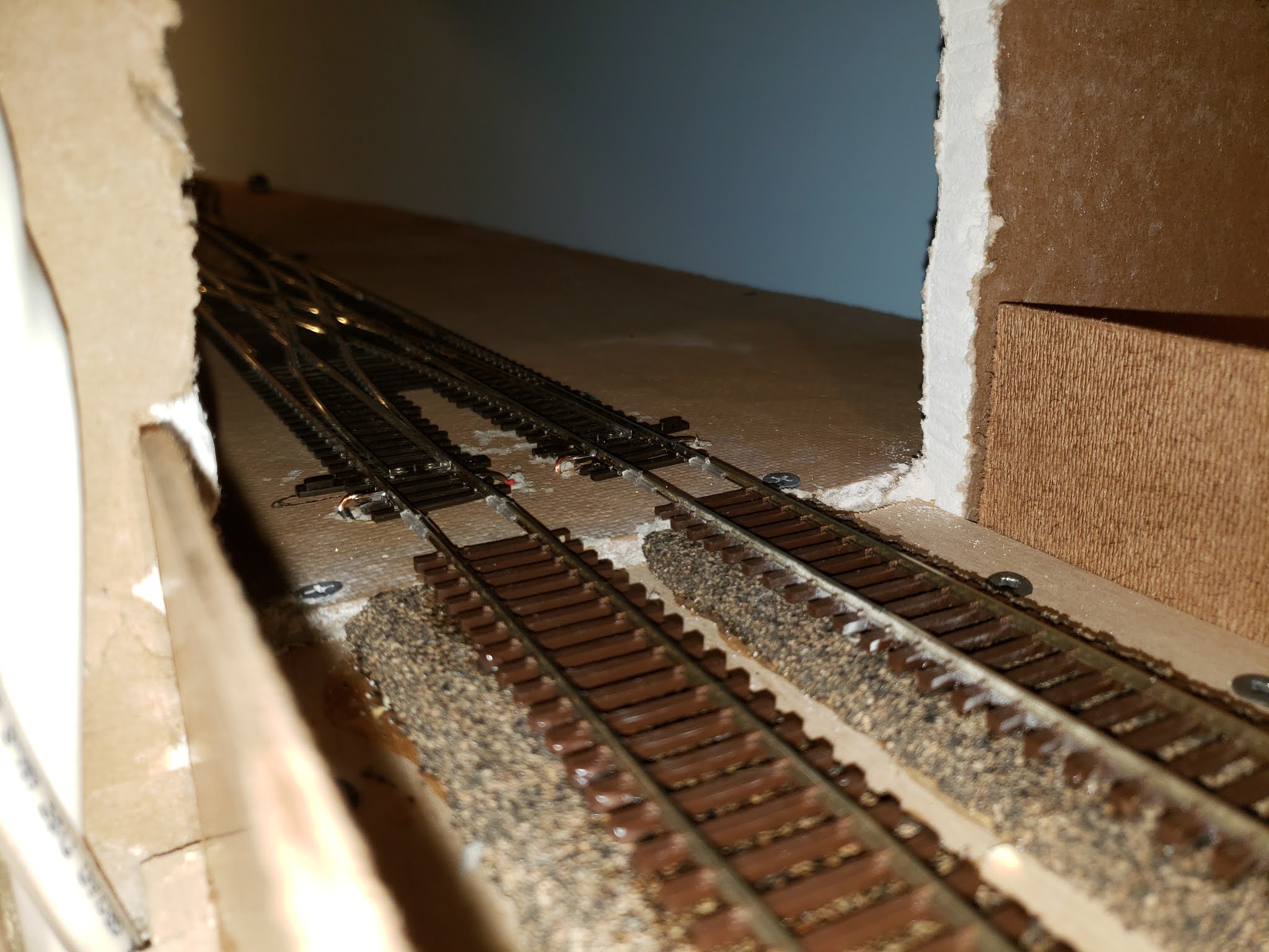


I arranged the double crossover on section U3 so that there would be room for the four Tortoise motors to go underneath and cut some connecting pieces of flex track to join it with the two parts of the staging yard. 


Now that the four turnouts are marked from the double crossover, the next step is to drill holes for the Tortoise throw arms to connect to the crossover. I'll also reinstall the flex track across the removable section. Once it's all dry (instead of using track nails, as I did the first time) I'll carefully cut the gaps to allow the section to be removed. Doing it this way will help ensure that the track remains aligned and eliminate those annoying derailments. 

7/11/2020 - I finished laying the track in the sump pump room and got all the track reconnected to the bus wires. Here's a tip -- make sure your wires are labeled. I had to trace wires around the room to figure out which was which, and quickly labeled them accordingly to avoid doing this again in the future. Once the track was done, I also cut the gaps for the removable section, did a little cleanup and was able to ensure that the section could be easily removed and replaced. Running some sensitive passenger cars through both sections of the track was also successful -- no derailments at all. 


7/12/2020 - I got the double crossover Tortoise motors wired up and successfully connected them to the Motorman board, which then let me control it from the computer. I also had mistakenly installed Tortoise drives under the layout without first wiring them, which meant I had to wire them under the layout. Not fun. However, I was able to get them connected with only a minor burn to my finger from the soldering iron. 


Within JMRI, I next step up track routes so that operators won't have to figure out how to throw up to four turnouts to get to each track. I set up routes 201-208 to connect tracks 1-8 to the outbound/eastbound main, and routes 211-218 to use the inbound/westbound main. Since the routes can be thrown from the Engine Driver app, this is far simpler than putting in a physical control panel. 

7/13/2020 - After getting the staging yard and sump pump room work done, my next task was to install the manual Tortoise controls on the Glenwood (U5-U6) district. I cut some Masonite fascia pieces at 5.5" tall. This gives me a small lip above the layout surface and a little bit of extra below to block the view of the wood supporting the section. 

Using my keyhole saw, I cut a 1" hole for the turnout control. I mounted the physical switch on a small piece of Masonite and then mounted that behind the hole. I like the effect and it protects the switch from being bumped. Flipping the switch up will switch to the spur and flipping it down will close the spur. After doing this one, I've got five more to do in the Glenwood district. 


7/18/2020 - I finished up the six local Tortoise controls over the past few nights. Those tiny DPDT switches are not the easiest things to solder. You need the smallest pencil tip for your soldering iron and I used a "helping hands" set of clamps to hold everything together. I'm planning to paint the fascia black but I'm happy with the installation design.


Operations

7/20/2020 - In a previous post, I talked about how I had backed off my computer-based switching system and had decided to use the Car Order System. After getting my initial three switching districts created and assigned car spots, I created car cards and completed the initial set of car card envelopes for them. The nice thing is that if I need to tweak a car card, it's easy to reprint. 


NMRA Achievement Program

7/6/2020 - I've earned the Author certificate already and submitted my paperwork for Chief Dispatcher last month. After updating my records, I determined that I had enough time units to submit my Volunteer achievement paperwork. I had to get some signatures from various people, but once those signed forms all arrived, I submitted them for review. Having that one done means I'm done with all the achievements that require you to track time. 

My next goal is the Electrical achievement. I'm almost done with the requirements already, with the exception of a reversing loop (item A3) and connecting up my circuit breakers (item A6). The nice thing about this achievement is that there's no judging involved. 

Tuesday, July 21, 2020

NMRA Achievement - Chief Dispatcher

My second NMRA Achievement Program certificate is the Chief Dispatcher certificate. This requires that you spend 60 hours in operating sessions performing jobs like dispatcher, road engineer, yardmaster, and several others. You also have to document an operations scheme for either a fictional or real railroad. I used my railroad (well, what I plan to build) as the sample. For more information about the requirements for this achievement, visit this site


Monday, June 8, 2020

June 2020 Journal

Trackwork

6/21/2020 - I installed the six Tortoise drives in sections U05-U06 after first prewiring them. I thought I was going to have to cut the 1x4 support piece, but then had a brainstorm -- all I had to do was to unfasten the support piece, slide it out of the way, and then resecure it after putting the Tortoises in. Easy peasy. I need to finish wiring the other four DPDT switches before I finish the installation. I think I will also cut fascia pieces so that I only have to cut a single hole through the fascia and 1x4 for the DPDT switch to be installed. 


Electronics / JMRI

6/1/2020 - As part of the JMRI installation, I soldered extension feeder wires to the six detection coils that need to be installed in the helix. Two of them will go into the new block 300 that I need to create, two will go into block 304, and two will go into block 305. This will bump the number of helix blocks up to 12 -- six in either direction. While this seems like a lot, it's really not. Each lap around the helix is 16-17 feet long, which is comparable to other blocks on the railroad. These blocks are longer since the trains will be running at "mainline speed" here, so having longer blocks works fine. 

6/7/2020 - I finished installing the feeders in the helix and getting them hooked up to the detection coils. I also took care of splitting what was block 301 into block 300 and 301. Block 300W and 300E now cover the track from the wall to the back of helix. After programming the Watchman board, it appeared in JMRI and I was able to add the remaining indicator tracks. 

In looking at the panel, there is a "temporary" link between block 204 (on the south wall) to blocks 305W/305E. In addition, on the lower deck, block 104 connects to block 300. This is only temporary until the peninsula is added onto the layout. At that point, there will likely be blocks 104-110 and 204-210, depending on how I lay out the track and blocks. 

Because there is a temporary link, I moved the indicator tracks for blocks 300-305 so that they connect with the turnout at the end of block 204. However, when I did that and started running trains through, it looked like the train was jumping from westbound to eastbound track. After I looked at the track, I realized that I actually had a right-hand switch and not a left-hand switch. Oops. Once I adjusted that and slid the tracks down, the train went where I thought it should be. 

Here's a snapshot of the new dispatcher panel as it stands now:


6/9/2020 - I did some work on cleaning up some kinks in the helix and adding the remaining feeders. After that, I tackled wiring up the microscopic DPDT switches for use with the Tortoises in the Glenwood (U5-U6) switching district. After a few failures, I figured out that I could bend the tabs out slightly to provide some extra space for the wires. I also soldered wires onto the 6 Tortoise drives that will be installed in this area. 

NMRA Achievement Program

6/5/2020 - After many hours of operating sessions, I finally got to the point of having more than enough hours for the Chief Dispatcher achievement. I had been putting off writing up all of the additional documentation on the layout, which is all documented here on the requirements document

While some of the NMRA requirements are focused on timetable-driven operations, going through the process did make me think about how the operations would work. A few things I learned/decided:
  • The mileage I was originally planning was way more than was appropriate for my layout. Originally, I was looking at Minneapolis to Minot, which was around 450 miles. Instead, I adjusted the layout down to a much smaller portion of the CP mainline, about 240 miles. 
  • For my branchline, I figured out that I could use the Twin Cities & Western railroad as the towns on that line. I have a pretty reasonable connection on the track schematic to connect the main to the branch, as well. 
  • It made me think about the sequence of trains, especially now that I've gotten my car card system in place. 
I wrote up my documents and submitted them for review, so hopefully in a few weeks (or months), I'll have my second achievement certificate. 

Thursday, May 14, 2020

May 2020 Journal

Trackwork


5/14/2020 - I finally came up with a design for the industrial/switching district in section L5. After ordering a few more turnouts, I laid the track and I'm happy with the overall design.


This photo shows where the industries can fit into this track arrangement.


Based on a suggestion from my friend Brad, the siding at the top will actually enter the building that's going into that space, plus there will be room on the outside for a few more car spots. The bottom track towards the left is primarily space for pulling cars out of the siding to the right, but once I get some power on the track, we'll see how many cars I can reasonably pull at once without having to move the cars to the left.

5/18/2020 - After the glue dried, I finished the section by adding feeders into all the track segments and between the various turnouts. I hadn't soldered in a while and the first joints showed, but I got the hang of it after a few bad connections. Once all the wiring was done and tested, I grabbed some cars from the main yard and put them into place. It looks like I'll be able to fit 19-20 cars in the district without losing the maneuverability to hit all the tracks. Here are some photos of the finished area.


Wiring/DCC


5/19/2020 - After getting the industrial district done, I went back to the helix room to diagnose my detection issue. The helix will have a total of 12 detection blocks, 6 in each direction, starting at 300W/300E and going up the helix to 305W/305E. When I last worked on this, I was getting what seemed like false readings on 302 that wouldn't go away. I went down some rabbit holes about whether the coils were too close, the wires were crossed, etc. After disconnecting the bus wires from the terminal strip, I had an engine continue running even when its bus wire was disconnected. I then proceeded to remove the other side's bus wires one by one and found that I had mixed up one pair of feeders. After making that fix, the detection started working properly again. 

I managed to get both sides of blocks 301, 302, 303 wired up with detection coils and got them connected to the Watchman board. In addition, I happened upon the Indicator Track feature in Panel Pro and replaced the somewhat awkward icons/lights with indicator tracks. The panel looks so much better doing this. I also got a reminder of JMRI's web server feature, which is also accessible from the mobile application. This made it a lot easier to test the detection since I didn't have to keep running out to the computer.

Unfortunately, I ran out of red 20 gauge wire and I'm running low on 3M suitcase connectors, so I'll have to wait a few days to restock my supplies. That's the first spool of 500 feet that I've run through, not sure if I'll need another one after the second spool, but we'll see. I get all my wire from Del City since you can order a variety of colors individually. 

The next steps are:
  • Split block 301 into two blocks -- block 300 will cover the track from the entry to the helix room around to the back wall of the helix.
  • Add feeders to block 300W and 300E and connect up the detectors to the Watchman board, which will finish out the 8 connections on that board. 
  • Program another Watchman board to accommodate blocks 304-305W/E and future blocks that will go into the peninsula. This board will be installed in the upper deck section prior to entering the helix, since that puts it in easy reach of peninsula blocks when I get those built. 
5/25/2020 - I spent today working on wiring for the lower deck. First, I extended the RR-Cirkits Simple Serial Bus (SSB) from the boards under the main yard around the corner to the staging yards on the north wall. I then extended the Tortoise power bus, since the RR-Cirkits Motorman boards require secondary power from a power supply. I added 22 gauge wires to each of the six Tortoise drives at my work bench, since that's far simpler than trying to solder under the deck.

After that, I was able to get the lower deck's Motorman board programmed and throwing the turnout that was previously installed under the first turnout in the throat. I installed a few more Tortoise drives and got those connected to the Motorman board. I still haven't figured out a good way to install Tortoise drives with only one pair of hands, but being able to throw the turnouts via the Engine Driver app is far easier than running back and forth to the computer.

In JMRI, I added those turnouts to the panel and after swapping the two power wires on the Tortoise drives, got them in sync with the panel. Since I've got three of the 7 turnouts wired now, I could try out the Routes feature of JMRI. This lets me create a route, say IR105 for staging track 5, and trigger it from the control panel or an Engine Driver throttle. This is simpler than having to throw all the turnouts individually. I still need to figure out how to put a button of some sort on the panel to trigger the route, but the basic logic works nicely.

The next step here is to finish the remaining four turnouts and get them wired into the Motorman board. In JMRI, I'll add routes for all eight staging tracks. After that, I'll wire up the Tortoise drives on the upper deck, although I first need to rework the yard entry using the double crossover I found in Minnesota last year. 

5/27/2020 - I wired up two additional Tortoise drives in the lower staging yard this evening. I also created the other routes so that I have one route per track in the lower yard. For the upper yard, since there will be a double crossover at the entrance, I'll end up with two sets of routes: one set to reach all eight tracks from the inbound/westbound main and one set to reach the tracks from the outbound/eastbound main. 

5/28/2020 - I finished wiring the last Tortoise drives in the lower staging yard and tested out all the JMRI routes. It's nice to have that work done. 

5/30/2020 - I finished wiring up the remaining Tortoise drives at the "west" end of the main yard and got them all connected up to JMRI. I can now control the entire yard from the dispatcher panel. I am planning to do a "proof-of-concept" with the push buttons to control the crossovers locally, as well. The idea is that the yardmasters will be able to use these controls as needed, but they're also available for the dispatcher to use. 

The lower deck JMRI control panel now looks like this, for now:


5/31/2020 - I soldered feeder wires onto six detection coils to be installed in the helix. I also "discovered" that I had a staple gun in my toolbox and replaced all the unreliable duct tape with staples to secure all the feeder wires. This cleans up the wiring quite a bit and lets the detection coils stay securely in place. 

Operations


5/26/2020 - I've been working on software that ties into my train management/inventory system that was showing promise in terms of random train generation, but after thinking how much computer interaction there would be, the ongoing tracking of car numbers, etc. I decided to give that up and switch to the car order system that Dan Hinel, Hank Tenwolde, Mike Wolf, and others are using. In this system, you deal with the type of car and focus on the car spots on industry tracks. The system is self-repairing and simpler since you are only looking at car types, not car numbers. While I'll still have a database of all my cars and locomotives, the computer won't be needed for car/train management during a session. 

I went through my three industry districts and identified 55 car spots and chose various types of cars to fill those spots. After the car is picked up at the location after loading/unloading, those cars will be sent out on either eastbound or westbound manifest freight trains. This simulates the load leaving the layout going to some other location and helps rotate car usage. 

I then ran trains to all three districts to adjust the cars on each of the industry spots and brought the remaining cars back to the main yard. The next step is to rotate the cards -- setouts become pickups, holds remain holds for one "turn" -- and then run local trains to pick up the cars that need to be moved. After that, I'll run manifest trains in either direction to pick those cars up and then I'll have a corrected car cycle to continue with. It'll be more interesting as I build out the peninsula and the additional twelve switching districts I'm anticipating, but this system lets me start operating on my own without having to constantly refer back to the computer. It's ironic that as a software developer that I'm choosing a manual system over a computerized one, but I'm looking more at the ongoing maintenance and choosing a simpler system. 

Tuesday, January 21, 2020

NMRA Achievement - Model Railroad Author

My first NMRA Achievement arrived in the mail today, the Model Railroad Author achievement. The points came from a split between this blog and my articles in OpSIG's Dispatcher Office publication, which I edit. For more information about the requirements for this achievement, visit this site


Tuesday, October 1, 2019

September 2019 Journal

Operations

9/5/2019 - I had a few friends over tonight to run trains, and I was pleasantly surprised how well everything ran. There are a few known issues on the layout, but they actually didn't find any additional ones. We did find that a few of the locomotives need to have their couplers switched to longer shank versions so that their walkways don't hit each other, but that's easy to take care of. We also ran into the somewhat obvious problem that you can't run all the trains out of one staging yard without taking an equal number from the other.

I have a few more sessions planned for the next few weeks where we'll do some more switching of trains/cars and I hope to have some more of my punch list items (especially Tortoise installation) done prior. It's good to have these sessions to keep up a little bit of healthy pressure to make progress on that list. 

Trackwork

9/5/2019 - As part of my punch list cleanup, I fixed a nasty kink that developed on the upper level of my helix. All the trains were derailing on it prior to the fix. I drilled some track nail-sized holes in the flex track, used a SweepStick to align the track, and put a bunch of track nails through the plastic ties. This got the track back into alignment and the derailments were no more. 

DCC/Electronics

9/3/2019 - I did a little bit of work tonight reinstalling the Digitrax UR92 wireless panel temporarily on the upper deck, where it will get less interference with people standing next to it. I also pulled out one of the standard Digitrax UP5 panels and investigated all the extra connections on it. While I didn't install the "keep alive" wire to it, I did add the track power indicator wires and connected it to my bus. Now when the power is on, the center light turns on. It's an easy way to tell that power is on if all the engine sounds are turned off. 

9/4/2019 - I knocked a few items off my punch list tonight -- connecting block 101 to the Watchman detector board, and fixing a crossover turnout wire that had gotten dislodged. I also decided to start running LocoNet wires so that I could install the remaining UP5 panels strategically around the layout. While I expect most people to use wireless throttles, certain things still work better with wired throttles, like switching yards and consisting/etc. locomotives. I installed a total of 6 panels on the lower deck and cut the connector cables between them. It took a little while to remember how you had to cut the wires to the 6 pin connectors, but once I got rolling, I got all the panels installed and wired to the layout. When I get the fascia cut and installed, the panels will be reinstalled on the fascia in their permanent locations, but the wires are long enough to allow me to move things around.

9/8/2019 - I was working on adding a new Tortoise drive to the upper deck mainline. In the process, I had turned on the power for the lights/DCC/etc. While I was working, I started smelling something strange, like burning plastic. I tracked the smell back to my Digitrax DT400 throttle and immediately turned everything off. Over the next few days, I worked with Digitrax support to determine that the command station and other hardware were OK, but the throttle got smoked. In addition, the computer interface seems to have gone south. Luckily the command station tested out OK, as did the UP5s and my Digitrax wireless UR92 device. Digitrax has great support and said they'd repair the throttle for $25, as opposed to buying a new one for almost $200.

The downside is that until I get the computer interface working, I can't really operate since all the turnouts are JMRI controlled. Hopefully I'll be back up and running in the next few weeks.

9/24/2019 - Got an email back from Digitrax acknowledging receipt of my throttle, but notifying me that it would be 60 days to get it back. They are blaming last year's hurricane for the delay. At least my LocoBuffer-USB will be back quicker, at which point I can turn on and off the layout without the big throttle. I'm borrowing one for now, but a lot of my punch list items are related to programming and wiring components to my RR-Cirkits components.


Friday, September 27, 2019

Givens and Druthers

If you've never heard the term before, the "givens and druthers" are the rules that you have made for how your railroad will be built and operated. It also describes what you're planning to model and perhaps even how you're planning to build the layout.

Setting

The Northstar Subdivision (NS Sub) is modeling the Canadian Pacific and BNSF mainlines from the Minneapolis/St. Paul area up to the northwest into North Dakota. While these two railroads have separate mainlines in reality, I have "merged" the two lines into a single mainline. Besides CP and BNSF, the railroad also interchanges with the Union Pacific and Canadian National railroads, as it does in real life. Pool power from other railroads will also make an appearance on the NS Sub. 

That said, when I first learned about operating sessions at the Purdue Railroad Club, each operating session would change the layout locations into a different railroad. As the scenery will be generic Midwest scenery, there's no reason that the destinations along the railroad could not be another region of the country. For instance, we might run from Chicago to Iowa on the Union Pacific, or somewhere on another railroad. The only real requirement is that there is enough motive power for the railroad to be realistic. 


Train Types

There will be both freight and passenger trains on the railroad. Amtrak's Empire Builder will traverse the route to and from Seattle. We'll also take some liberty with reality and have VIA Rail trains going from the Twin Cities to Winnipeg, as well as a Canadian Pacific "heritage" train that can make the rounds as a fan trip. I will also be hosting some truly foreign engines, as I'm a fan of German Rail (Deutsche Bundesbahn) trains. We'll ignore the pesky fact that those trains are electric and chalk it up to hidden third rail. This will be another fan train owned by a museum somewhere along the line. Passenger trains will get priority on the NS Sub, unlike in real life. 

I'm also planning to add some passenger stations to the railroad, although I don't think I have space for a large passenger terminal. Passenger train crews will be required to make station stops during their journeys. 

Freight trains will be broken into three categories:
  • Run-through trains with no switching -- intermodal and unit coal trains for starters. 
  • Manifest freight trains that will switch cars only at yards.
  • Local trains that will work industries. 
Manifest freight trains do not work industries. They drop and pick up cars at yards only. Locals are responsible for moving those cars to and from the industry tracks. There will be far more rail-served industries than likely exist in real life, but as this is primarily an operations-focused railroad, that's to be expected. Freight trains arriving at the main yard will need to take their power to get serviced, as the yard represents a major stop on each train's trip. 

There may also be "special" trains that inject variety into the operating session, such as work trains that block a particular part of the line. 


Standards

  • Atlas code 83 track - concrete color for mainlines, wood color for all other track
  • Mainline turnouts - #8, all other turnouts
  • Minimum radius on visible track: 30"
  • Maximum train length is governed by staging yard track lengths, but 11-12' is roughly the maximum length. 
  • Mainline track blocks are all detected through JMRI and RR-Cirkits products. 
  • Mainline turnouts will be controlled both from dispatcher's panel (via JMRI) and with lineside pushbutton controls. The pushbutton controls will be considered out of service during operating sessions if a dispatcher is present. 
  • All mainline turnouts and turnouts that are out of easy reach will be powered using Tortoise drives. 
  • Layout will eventually be signaled through JMRI and RR-Cirkits products.
  • Wiring Standards - See this article
  • Benchwork Construction - See this article 
  • Visual indicators will be added to the layout to help identify the block divisions. 

DCC

  • Digitrax DCC is the command system in use on the layout. 
  • JMRI is also installed, allowing for Wi-Fi throttles. 
  • Yard operators will have wired utility throttles (UT4) for responsiveness. 
  • UT4D throttles are already available for operators to use. 
  • Command throttles (DT400, DT500, etc.) should be restricted to avoid programming issues during an operating session. 

Motive Power

  • Each locomotive will be assigned an engine card with instructions on how the DCC functions work. Engines that are consisted will have their cards clipped together with the addressable engine card on top. 
  • In general, locomotives will be assigned in pairs for manifest freight trains. Locals may use single engines if they don't have to traverse the helix or if the train is less than 10 cars. 
  • Engines will all have reversing headlights, which helps determine if the locomotive is answering to DCC commands. 
  • Engines with sound will have their sound turned down so that an engineer walking along side can hear it, but so that it can't be heard across the room. 
  • Engines should be muted when they are not in use, either through the appropriate command function or through a kill switch on the track. 

Signals

  • While hooded signals are more modern, ensure that they are easily visible from the engineer's point of view. May need to angle them slightly out towards the aisle, or install "repeaters" on the fascia. 
  • We are not following a particular prototype for signals. Most signals in the Midwest use the colors and not positions for their indicators. Some Canadian signals use a single multicolored light, but the specific signals used on the layout will be dictated by what models are available for purchase.